E-mail : sale@coslan.com

Tel : (020)38104418

Patch Clamp Recording System


  • Independent V-hold and I-hold circuitry (3 operating modes)
    • V Clamp Mode: Input is clamped to a maximum of ±1 V. Commands are the sum of the holding voltage and any external input signals.
    • Zero Current Mode: Bridges the voltage and current clamp modes. All commands are inactive except the junction zero, which functions in this case as an offset control for the electrode and tip potentials associated with the pipette.
    • I Clamp Mode: In the current clamp mode, active commands are the current hold and any external command input signals, summed. Clamp stability is enhanced with the selection of three clamp speeds.
  • Compensation Controls
    • Voltage Offsets (including junction potentials): Automatically compensated with the auto zero or manually with the junction zero.
    • Capacity Compensation: Paired controls; fast (0-5 µs), medium (0-2 ms) and slow (0-20 ms) compensate the current transient caused by a step command signal. Each pair has a separate control for amplitude and time constant.
    • Series Resistance: Signal errors contributed by the electrode (access) resistance in whole cell recording are subtracted from the output with the series R comp control. The compensated resistance (0-100 MΩ) is read from a ten turn dial.
    • Leak Subtract: Used to compensate leakage current due to the voltage drop across the seal (shunt) resistance.
  • 4-pole low-pass Bessel filter
  • Internally generated test signals
  • Variable duration zap circuit


  • Product overview
  • Product parameters
  • Product features
  • Product application

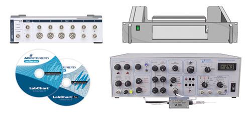
    Patch Clamp Recording Systems with a choice of 3 Headstages are suitable for measuring currents in whole cell measurements and single channel studies. Microelectrodes or glass electrodes/micropipettes are not supplied. Other resistive-feedback headstages are also separately available for use with the Patch Clamp Amplifier.


    • Independent V-hold and I-hold circuitry (3 operating modes)
      • V Clamp Mode: Input is clamped to a maximum of ±1 V. Commands are the sum of the holding voltage and any external input signals.
      • Zero Current Mode: Bridges the voltage and current clamp modes. All commands are inactive except the junction zero, which functions in this case as an offset control for the electrode and tip potentials associated with the pipette.
      • I Clamp Mode: In the current clamp mode, active commands are the current hold and any external command input signals, summed. Clamp stability is enhanced with the selection of three clamp speeds.
    • Compensation Controls
      • Voltage Offsets (including junction potentials): Automatically compensated with the auto zero or manually with the junction zero.
      • Capacity Compensation: Paired controls; fast (0-5 µs), medium (0-2 ms) and slow (0-20 ms) compensate the current transient caused by a step command signal. Each pair has a separate control for amplitude and time constant.
      • Series Resistance: Signal errors contributed by the electrode (access) resistance in whole cell recording are subtracted from the output with the series R comp control. The compensated resistance (0-100 MΩ) is read from a ten turn dial.
      • Leak Subtract: Used to compensate leakage current due to the voltage drop across the seal (shunt) resistance.
    • 4-pole low-pass Bessel filter
    • Internally generated test signals
    • Variable duration zap circuit


相关产品

Contact Us

  • GuangZhou

    Phone :

    (020)38104418

    Address :

    Room 2903, Block H, Autoland Winter Plaza, No. 12, Zhujiang East Road, Tianhe District, Guangzhou

  • Hongkong

    Phone :

    00852-26681868

    Address :

    Room 803, Chevalier Building, 45-51 Chatham Road South, Tsim Sha Tsui, Kowloon, Hong Kong

  • ShenZhen

    Phone :

    0755-26419087

    Address :

    Room 1623, Dongming Building, No. 284 Minkang Road, Longhua District, Shenzhen

Message